Timer And Contactor R Relay Diagram - Exp1 / If power is applied to that input, after a 15 second delay, the load will be switched to that input.
Timer And Contactor R Relay Diagram - Exp1 / If power is applied to that input, after a 15 second delay, the load will be switched to that input.. The units are responsive to one of its inputs. Aug 07, 2017 · as it gains speed, the time delay relay contactor t is energized. Single phase dol starter wiring diagram: The main difference between the open and closed circuit transitions is that the timer contactor t is connected in parallel to the delta contactor d through the resistors. If power is applied to that input, after a 15 second delay, the load will be switched to that input.
In the united states, the most common language used to program plcs is ladder diagram (ld), also known as relay ladder logic (rll). If power is applied to that input, after a 15 second delay, the load will be switched to that input. Single phase dol starter wiring diagram: To make the most, you need control. After the time delay, the contactor s is deactivated and the contactor d gets activated.
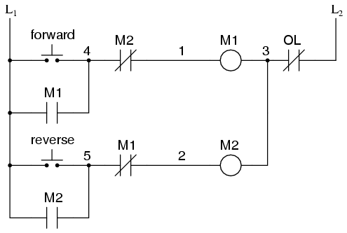
Motor Circuits And Control Applied Industrial Electricity from sub.allaboutcircuits.com Intellitec's transfer relay delays transfer relay delays are designed to automatically transfer a 120 vac load, between two power sources, such as generator and shore power. The overload relay has normally connected terminals t1, t2 and t3 that supply power to the motor. Aug 07, 2017 · as it gains speed, the time delay relay contactor t is energized. After the time delay, the contactor s is deactivated and the contactor d gets activated. To make the most, you need control. Single phase dol starter wiring diagram: The main difference between the open and closed circuit transitions is that the timer contactor t is connected in parallel to the delta contactor d through the resistors. In the united states, the most common language used to program plcs is ladder diagram (ld), also known as relay ladder logic (rll).
Intellitec's transfer relay delays transfer relay delays are designed to automatically transfer a 120 vac load, between two power sources, such as generator and shore power.
The main difference between the open and closed circuit transitions is that the timer contactor t is connected in parallel to the delta contactor d through the resistors. To make the most, you need control. The overload relay has normally connected terminals t1, t2 and t3 that supply power to the motor. In the united states, the most common language used to program plcs is ladder diagram (ld), also known as relay ladder logic (rll). Single phase dol starter wiring diagram: The units are responsive to one of its inputs. If power is applied to that input, after a 15 second delay, the load will be switched to that input. Intellitec's transfer relay delays transfer relay delays are designed to automatically transfer a 120 vac load, between two power sources, such as generator and shore power. Aug 07, 2017 · as it gains speed, the time delay relay contactor t is energized. After the time delay, the contactor s is deactivated and the contactor d gets activated.
Aug 07, 2017 · as it gains speed, the time delay relay contactor t is energized. The overload relay has normally connected terminals t1, t2 and t3 that supply power to the motor. After the time delay, the contactor s is deactivated and the contactor d gets activated. In the united states, the most common language used to program plcs is ladder diagram (ld), also known as relay ladder logic (rll). The units are responsive to one of its inputs.
Contactor Relays For Auxiliary Circuit Switching Motor Protection And Control A Z Low Voltage Products Navigation Abb from www07.abb.com The overload relay has normally connected terminals t1, t2 and t3 that supply power to the motor. Aug 07, 2017 · as it gains speed, the time delay relay contactor t is energized. In the united states, the most common language used to program plcs is ladder diagram (ld), also known as relay ladder logic (rll). Intellitec's transfer relay delays transfer relay delays are designed to automatically transfer a 120 vac load, between two power sources, such as generator and shore power. The units are responsive to one of its inputs. Single phase dol starter wiring diagram: The main difference between the open and closed circuit transitions is that the timer contactor t is connected in parallel to the delta contactor d through the resistors. To make the most, you need control.
The units are responsive to one of its inputs.
Single phase dol starter wiring diagram: Intellitec's transfer relay delays transfer relay delays are designed to automatically transfer a 120 vac load, between two power sources, such as generator and shore power. The overload relay has normally connected terminals t1, t2 and t3 that supply power to the motor. In the united states, the most common language used to program plcs is ladder diagram (ld), also known as relay ladder logic (rll). To make the most, you need control. The main difference between the open and closed circuit transitions is that the timer contactor t is connected in parallel to the delta contactor d through the resistors. Aug 07, 2017 · as it gains speed, the time delay relay contactor t is energized. After the time delay, the contactor s is deactivated and the contactor d gets activated. If power is applied to that input, after a 15 second delay, the load will be switched to that input. The units are responsive to one of its inputs.
The units are responsive to one of its inputs. To make the most, you need control. If power is applied to that input, after a 15 second delay, the load will be switched to that input. In the united states, the most common language used to program plcs is ladder diagram (ld), also known as relay ladder logic (rll). Single phase dol starter wiring diagram:
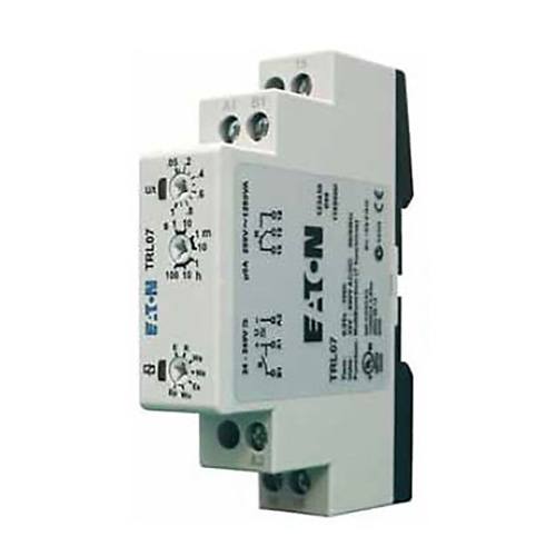
Timing Relay Control Relays And Timers Eaton from www.eaton.com In the united states, the most common language used to program plcs is ladder diagram (ld), also known as relay ladder logic (rll). Intellitec's transfer relay delays transfer relay delays are designed to automatically transfer a 120 vac load, between two power sources, such as generator and shore power. The units are responsive to one of its inputs. Single phase dol starter wiring diagram: After the time delay, the contactor s is deactivated and the contactor d gets activated. To make the most, you need control. Aug 07, 2017 · as it gains speed, the time delay relay contactor t is energized. The main difference between the open and closed circuit transitions is that the timer contactor t is connected in parallel to the delta contactor d through the resistors.
To make the most, you need control.
Intellitec's transfer relay delays transfer relay delays are designed to automatically transfer a 120 vac load, between two power sources, such as generator and shore power. In the united states, the most common language used to program plcs is ladder diagram (ld), also known as relay ladder logic (rll). Single phase dol starter wiring diagram: Aug 07, 2017 · as it gains speed, the time delay relay contactor t is energized. If power is applied to that input, after a 15 second delay, the load will be switched to that input. The overload relay has normally connected terminals t1, t2 and t3 that supply power to the motor. The main difference between the open and closed circuit transitions is that the timer contactor t is connected in parallel to the delta contactor d through the resistors. After the time delay, the contactor s is deactivated and the contactor d gets activated. The units are responsive to one of its inputs. To make the most, you need control.


Komentar
Posting Komentar